The Safest, Most Reliable, Easiest to Install, Most Versatile Cable Bus Power Feeder System on the Market.
CSA C22.2 No. 273 Certified Cablebus.


United Wire & Cable has developed a complete unarmoured power cable ventilated enclosure system that provides a one-stop solution to the challenge of transferring power from one point to another at a very low installed cost to the system owner. This system is called the MAXIAMP® Cable Bus Feeder System and is superior to bus duct, armoured cable in tray, underground duct bank, direct buried and conduit systems.
In the past, Electrical and Industrial plants transporting Power between two points locally such as from a Generator to a Transformer substation or from the Substation to various distribution points, have resorted to many solutions. One of the most common methods has been to use Armoured Cable in an open “tray” structure installation. In order to do this they have had to source cable trays from a fabricating shop, power cables from wire and cable experts, design the layout according to codes and Contractors to supply enclosures and install the equipment.
MAXIAMP® is a uniquely designed cable bus feeder system package which includes technically selected power cables, a well ventilated aluminum or steel enclosure, all associated hardware, entry fittings, and cable terminations (including an insulation shield and conductor lugs); tailored to be an effective and highly engineered product. This unique lug-to-lug solution simplifies and streamlines the project managers’ task tremendously.
Cable Bus is an assembly of insulated cable conductors designed as a system to transmit electrical current and to withstand the effects of specified system requirements, such as short-circuit current, circuit loading, bonding, with fittings and conductor terminations in a completely enclosed, ventilated protective metal housing.


With the extensive expertise of United Wire & Cable in the design, manufacture and application engineering of power cable products and the development and installation of cable enclosure systems, we are confident that MAXIAMP®offers the most reliable, versatile and cost effective cable bus feeder system in the world market. Our exclusive MAXIAMP®design provides significant advantages over the competition
Enclosure
The enclosure has been built from the ground up thinking about you, the client. We have followed up with many system installations and have gone through countless design tweaks to provide the most robust, flexible environment resistant enclosure in the market today.
| Design | MAXIAMP® Advantage |
| Multi-tiered I-Beam frames, bolted on top of each other, interconnected with out unique rungs spaced one foot apart | Provides the highest ratio of strength/weight tray in the market. This allows the system to be in the best possible position to withstand any system electrical fault forces that may occur. |
| Bonding conductor is housed within the enclosure | Prevents theft and reduces exposure of the bonding conductor to the outside elements. |
| Louvered slots on both top and bottom of tray | The slots increase air flow, allowing the MAXIAMP® Cable Bus System to achieve a free air rating, reducing costs on the cable. The louvered slots prevent foreign objects from falling into the enclosure that would have otherwise fallen in with cutout holes. |
| Peaked covers for outdoor environments | Allows water (rain, snow) and other foreign objects to run off the side of the tray rather than accumulate on the tray. This reduces weight over the system and is especially useful on long outdoor runs. |
| Enclosure widths from 9″-36″ | Whatever your system requirements are, the MAXIAMP® Cable Bus System can accommodate it. The MAXIAMP® Cable Bus System can even support multiple circuits in one tray through the use of Cable Barriers (see Cable Barriers) |
| Available in Aluminum, Galvanized Steel, Epoxy coated Galvanized, and Stainless Steel enclosures | The MAXIAMP® Cable Bus System can handle all kinds of environments including heavily corrosive ones. |
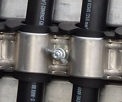
MAXIAMP® OP (One Piece) Clamp System
The MAXIAMP® OP Clamp System is a tool-free innovation of United Wire & Cable that is a revolutionary way to hold cables within a cable bus that allows for maximum support, maximum safety, and easier installation.
| Design | MAXIAMP® Advantage |
| Made of a light weight, pre-formed metal clamp | Designed to securely fit a wide range of power cable MAX / MIN O.D. tolerances. Acts as a heat sink to keep cables cooler. Also provides an easy path to ground to initiate a quick system break. Most importantly, such a clamping method avoids potentially disastrous phase to phase cable fault. The system allows for quick dissipation of fault currents from the cable to enclosure and to the bonding cable should a short-circuit fault occur. |
| Non-magnetic metal is used for the clamp | The conductor cables are not encircled with magnetic metal and therefore do not encounter hysteresis/eddy current losses. |
| Special clamp end design spacer | Simply positions the phase conductors in trefoil rotating configurations which ideally cancels out the electromagnetic flux generated by each cable to ensure identical cable impedances for equal ampacity load sharing, minimal loss and voltage drop. |
| Spring loaded holder bolts | Ideal and flexible placement of cables without any tools and in a matter of seconds. |
| Self centering wing nuts | Specifically designed with feedback from clients to make installation easy. The self centering wing nuts do not fall off the bolt and have a serrated bottom to bite into the clamp, resulting in a tool-free method of clamping the cables. |
| Rubber grommets for vertical applications | Specially designed to support the weight of the cables on long vertical runs. |
Cable Support Rungs
While most cable bus manufacturers use a block system, the MAXIAMP® Cable Bus utilizes smooth metal rungs that has numerous advantages over the competition.
| Design | MAXIAMP® Advantage |
| Rungs are spaced one foot apart | Greatly reduces sag and sidewall pressure stress on the cables and the cable’s insulation while allowing for easier installation of the cables. An added benefit is that the rungs will also support the cables during in-rush and fault current conditions. |
| Flexible clamping intervals | Allows for shorter or longer clamping intervals, as deemed necessary. United Wire & Cable recommends clamping every 4 feet for horizontal spans and every 2 feet for vertical spans. |
| Offset rungs from tier to tier | Allows removal or placement of cables on different levels without disturbing cables on other levels. |
Multi-Circuit Metal Barrier
Unique to MAXIAMP® Cable Bus System, the multi-circuit metal barrier allows for multiple circuits within one enclosure that saves money, time, and space.
| Design | MAXIAMP® Advantage |
| Metal Barrier | Allows for servicing of one circuit while leaving the other circuit live. The metal barrier will protect the technician, effectively separating the two circuits. |
| Space savings | When space is a premium, having one MAXIAMP® Cable Bus System with multiple circuits will greatly reduce the footprint required. |
| One enclosure | Significant cost savings in both material and installation due to only one enclosure needed. |
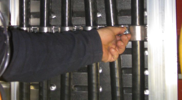
Installer clamping down cables with our special self centering wingnut… No tools required!
A few key features of a MAXIAMP® Cable Bus System that enhance the ease, speed, flexibility, and reliability of the system installation are as follows:
Installer Friendly System
The MAXIAMP® Cable Bus system design is based on the same construction as a ladder type Cable Tray with rungs, which almost all electrical installers are well experienced with in terms of system structural supports, site tailored enclosure adjustments, cable-pulling techniques, positioning and clamping. This provides an installer with a comfort level and the ability to produce a highly reliable and trouble free installation cable power delivery system.
Site Installation Flexibility
The sturdy two level four “I” beam enclosure consisting of wide and smooth cross member cable rungs welded to the “I” beams on both levels, spaced one foot apart, can be cut to any desired length at site with ease and without any concern about long cable support gaps.
Speedy and Simplified Cable Pulling
The smooth short span cable rungs, which provide optimum close proximity cable supports, are designed for straight long cable pulls without the need of installation of a series of cable rollers, normally required to prevent cable damage during cable pulling.
Easy Multi-level Access During and After Installation
Each level of cable rungs are staggered by 6” from level to level to allow for ease in clamping or removing cables at any time during or after installation without the need to dismantle any part of the system.
Quick and Easy Cable Positioning and Securing
The lightweight, one piece pre-formed cable pre-spaced positioning and securing clamp is effectively connected to the rung with an easily positioned spring-loaded bolt and self-centering wing nut that is hand tightened. No tools are required, allowing for ease of installation in both open and limited working spaces.
Cable Clamp Spacing Flexibility
The one piece metal clamp not only serves as an electrically conductive path to the enclosure bonding conductor to ensure a rapid system break in the event of a highly unlikely cable fault, but also allows the installer the flexibility to clamp the cables at any intermediate one foot spaced cable rung if additional clamping is deemed to be necessary by the installer, especially in vertical circuit sections. Cable clamp spacing in horizontal runs is normally every three or four feet.
Installation Ease in Forming Cable Phase Trefoil Configuration
The pre-formed one-piece cable clamps are designed for installer ease and flexibility in forming a rotating cable phase trefoil configuration of the paralleled cables to ensure the lowest possible system reactance through effective cancellation of the cable current generated electromagnetic flux.
Ease of Site Installation Deviations Around Unexpected Circuit Route Obstacles
In many instances installers encounter unexpected obstacles placed in line with the system circuit route unbeknown to the system designer. The MAXIAMP® system allows the installer to simply and easily deviate around the obstacle with readily available hinged horizontal and vertical adjustable tray enclosure plates.
Easy and Well Protected Installation of MAXIAMP® System Bonding Conductors Within Enclosure
Stranded bare copper bonding conductors are easily pulled over the top level of the smooth cable rungs throughout the circuit length and connected to the inside wall of one of the top MAXIAMP® enclosure “I” beam with supplied compatible ground clamps. Installation within the enclosure is not only easier but eliminates the risk of unanticipated removal, metal theft, as well as excessive exposure to corrosion.
Easy, Quick, and Reliable Installation of Pre-Designed and Assembled Dust and Weatherproof Entrance Plates.
Pre-designed, pre-drilled, and pre-assembled circuit end entrance plates, complete with pre-positioned and assembled dust and weatherproof cable entrance connectors, gasketing, pre-drilled attachment holes including connecting hardware are provided for an easy, quick and reliable entrance installation.
Easy Installation of Enclosure Top Covers
The system enclosure indoor louver ventilated flat covers and the peaked roof outdoor covers, which the latter is designed to effectively allow rainfall to wash any accumulation of debris or dust off, are easily and quickly installed with metal tap screws provided. In addition, for system safety, during and after installation, the louvered covers disallow entry of any penetrable objects at greater than 45 degrees off horizontal.
The MAXIAMP® Cable Bus System as built with safety in mind. Here are some of the reasons that MAXIAMP® is the safest cable bus system in the market today:
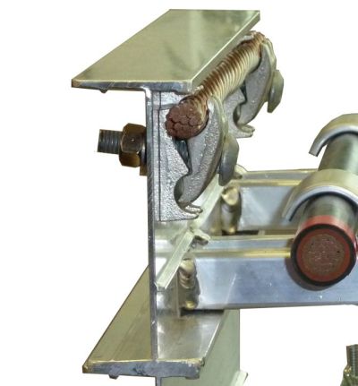
MAXIAMP I-Beam and Bonding Wire
I-Beams
The I-Beam provides a highly stable and rigid frame that can withstand high winds and weight increases.
Bonding Wire
Bonding wire runs along the inside of the enclosure to prevent wire theft.
Louvered Holes
The holes are louvered so that foreign objects cannot fall into the enclosure.
Fire Rating
Cables are rated for FT4. MAXIAMP® Cable Bus System has a FT3 wall penetration solution that is quick to install.
No Tools Needed to Clamp Cables
No tools around cables means virtually no chance of damaging the insulation, which could lead to faults.
MAXIAMP Rubber Grommets
Rubber Grommets
Rubber grommets allow for long vertical runs without the concern of cables slipping from the clamps.
Fault Clearing
With metal rungs and clamps, any fault that occurs along the circuit will have a clear path to ground, which enhances safety by clearing the fault quickly.
No Controlled Environment Required
Unlike bus duct, the MAXIAMP® Cable Bus System does not need a controlled environment to operate properly.
MAXIAMP® Cable Bus systems are applicable for almost every possible power delivery requirement, and are superior to all of the following possible systems:
- Armoured or Sheathed Cable in Open Tray
- Direct Burial
- Underground Duct System
- Conduit
- Bus Duct
Here are some reasons why MAXIAMP® Cable Bus offers significant advantages over these different installations:
1. Armoured or Sheathed Cable in Open Tray vs. MAXIAMP® Cable Bus
| Armoured or Sheathed Cables | MAXIAMP® Cable Bus |
| armoured cables result in larger O.D. requiring wider tray as well they need a larger bending radius | unarmoured and smaller size of cables leads to a much smaller bending radius |
| cables are difficult to pull due to the armour and the additional weight loading must be considered for installation | the unarmoured cables are lighter and easier to pull. |
| requires special armour/sheath treatment at the terminations | no such processes required |
| difficult to maintain proper cable spacing and positioning to meet heat transfer and electrical field balance requirements (critical factors for trouble free cable operation and longevity) | cables are properly spaced and positioned using our unique MAXIAMP® OP clamps, maximizing electrical field balance |
2. Direct Burial vs. MAXIAMP® Cable Bus Underground System
| Direct Burial | Below Grade MAXIAMP® Cable Bus |
| required cable spacing between cables and multiple circuits demand a significant amount of real estate. There is an increased risk of natural and/or man-made obstacles due to the size of the trench. Typical trenching requirements are 16 feet wide (tapered for safety) and 5+ feet deep. | compact and small system requiring very little, if any, excavation space. Minimal risk of natural and/or man-made obstacles due to the small trenching requirements. Typical trenching requires are 40 inches wide by 30 inches deep. |
| allowable cable ampacity per conductor is substantially lower due to lack of free air rating. | highest possible allowable ampacity per conductor based on free air rating – approximately 50% more ampacity than a direct burial installation |
| adding more cable circuits after installation is a difficult, risky and an intensive process. Tracking existing cables and reorganization of cables required with a high risk of damaging existing cables. | adding more cable circuits after installation is very simple with accessible lids to the MAXIAMP® enclosure. |
| replacement of a failed cable is very complicated, with a lengthy downtime. Tracking of the fault cable is difficult and risk of damaging other cables is high. | replacement of any of the cables would be simple, fast, and with minimum downtime. |
3. Underground Duct System vs. MAXIAMP® Cable Bus Underground System
| Underground Duct Bank | Below Grade MAXIAMP® Cable Bus |
| required cable spacing between cables and multiple circuits demand a significant amount of real estate. There is an increased risk of natural and/or man-made obstacles due to the size of the trench. Typical trenching requirements are 16 feet wide (tapered for safety) and 5+ feet deep. | compact and small system requiring very little, if any, excavation space. Minimal risk of natural and/or man-made obstacles due to the small trenching requirements. Typical trenching requires are 40 inches wide by 30 inches deep. |
| low allowable ampacity ratings due to restricted cable heat dissipation. | highest possible allowable ampacity per conductor based on free air rating –approx. 60% to 80% more ampacity than concrete encased duct system. |
| ability to expand or repair the duct system after installation can be very difficult, restrictive, disruptive and expensive due to the need for more real estate. | simple, easily accessible and inexpensive to expand system with additional cables at a later date. |
| ducts may shift and/or shear due to ground movement, damaging the cables. | MAXIAMP’s® interlocked concrete encasement and I-beam enclosure design effectively protects the cables during ground movement. |
| pulling cable through bends introduces risk of excessive pulling tensions, side wall pressure and potential cable tearing action by foreign objects in the duct | cable can be pulled or laid in place with ease and always visible during installation as well as for visual inspections after installation. |
| volatile gases entering a duct system can transmit from one area to another | any gases entering the encasement enclosure will vent at or near the point of entry. |
4. Conduit vs. MAXIAMP® Cable Bus
| Conduit | MAXIAMP® Cable Bus |
| lower allowable ampacity per conductor due to heat buildup from trapped air. | highest possible allowable ampacity per conductor due to free air rating. |
| cable is subject to damage during cable pulling operation due to sharp edges and excessive side wall pressure | no risk of cable damage during installation due to complete visibility and full control of cable movement on a smooth controlled surface |
| additional cable circuit would require a new conduit system due to conduit cross sectional fill limitations | existing system capable of accommodating additional cables with ease and with minimum downtime |
| pulling lengths are restricted depending on the number of bends. | no pulling restrictions are necessary. |
5. Bus Duct vs. MAXIAMP® Cable Bus
| Bus Duct | MAXIAMP® Cable Bus |
| very expensive to design and install due to circuit length tolerances and on-site replacement requirements. Quickest lead time on bus duct system is 12 weeks. | inexpensive system that provides plenty of tolerance and flexibility during design and is easily adjustable on-site. Lead time on the MAXIAMP® Cable Bus system is as short as 3 weeks. |
| construction consists of bare metal conductors on insulators which are readily subject to arcing and tracking problems where moisture, sprinklers systems, and dust exists. | insulated conductors in the MAXIAMP® Cable Bus system are designed to negate any such problems. |
| need for additional load current after initial installation requires either an expensive continuous cooling system throughout the circuit or a complete replacement of the circuit system. | inexpensive additional cables can be installed quickly and easily to meet the higher load current. |
| the mechanically assembled bus duct system is prone to failure in areas of vibration. | vibration is not a critical operating factor in the MAXIAMP® Cable Bus system due to the conductor and enclosure flexibility. |
| thermal expansion and contraction is a major cause of bus duct system breakdown. | enclosure and cables are designed to counteract thermal expansion and contraction. |
| system electrical faults per phase conductor cause significant mechanical forces to occur in each phase bus leading to loosening of the connections and stressing the conductor support insulators. This can lead to catastrophic failure of the bus duct system. | system electrical fault currents are divided into smaller magnitudes and shared equally amongst paralleled conductors, reducing potential mechanical forces. |
| requires annual maintenance. | no maintenance required. |
| designed only for low-medium voltage. | designed for all voltage levels (upto 230kV) and high amperage loads. |
The MAXIAMP® Cable Bus System is a ventilated fully, enclosed unarmoured insulated Power Cable free air ampacity rated system that is pre-engineered and supplied as a full package of specially designed compatible CSA certified components, accessories, and hardware required for site assembly as a complete power delivery system. This system is free air ampacity rated in either overhead or underground installations or as a combination of both installation methods in the same circuit run, allowing for a continuous uninterrupted power feeder circuit. The key components supplied in the system packages are:
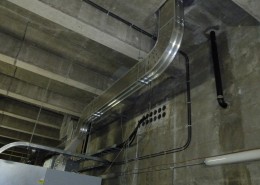
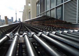
Section A – Above Grade Free Air Ampacity MAXIAMP®Systems
Overhead Free Air Ampacity MAXIAMP System
- Metal Enclosure – Special CSA certified multi-level enclosure provided in a combination of straight, fixed, and adjustable bend sections consisting of at least 4 “I” beams and specially vented top and bottom covers. Flat vented covers are supplied for inside building circuit installations and peaked slope roof vented covers for outdoor installations, allowing debris to be washed off by rainwater.
- Insulated Power Cables (600V to 230 kV)– Specially engineered and CSA certified, unarmoured easy bending and handling Ethylene Propylene Rubber insulated Power Cables requiring specific dimensions and fire ratings.
- Cable Clamping – Specially dimensioned and pre-formed one piece multiple loop clamps c/w hardware for automatically establishing rotating balanced flux trefoil phase cable impedance relationships and providing easy installation without the need for any tools to secure clamps in place.
- System Bonding Conductor – Stranded bare copper conductor sized to meet the CE Code requirements c/w clamps for installation within the enclosure from end to end of the system circuit.
- Weatherproof Entrance Plates – Pre-sized and pre-drilled metal plates c/w pre-assembled compatible watertight cable entrance fittings, gaskets and all required connecting hardware.
- Phase Conductor Terminal Lugs – Two hole long barrel double compression lugs to ensure equal terminal resistance of each paralleled phase conductor during load cycling, resulting in assured equal conductor load sharing.
- Fire Barriers – Weatherproof fire barriers with 3-hour fire ratings.
- Shielded Power Cable Terminations – Pre-engineered compatible insulation shield terminators for shielded Power Cable voltages of 5 kV to 230 kV
- Circuit Drawings – Cable Bus enclosure isometric circuit drawings provided for final approval.
- Installation Manual – An installation manual for site assembly of the Cable Bus System shall be provided to the installer, showing required cable positioning, assembly procedures and any other guidelines necessary to ensure a proper Cable Bus System site assembly.
- Exception(s) – System site external supports shall be provided by the installer.
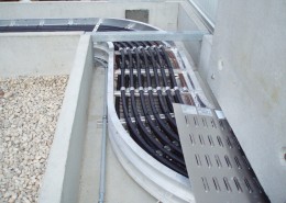
Section B – Below Grade Free Air Ampacity MAXIAMP® Cable Bus Systems (Proprietary)
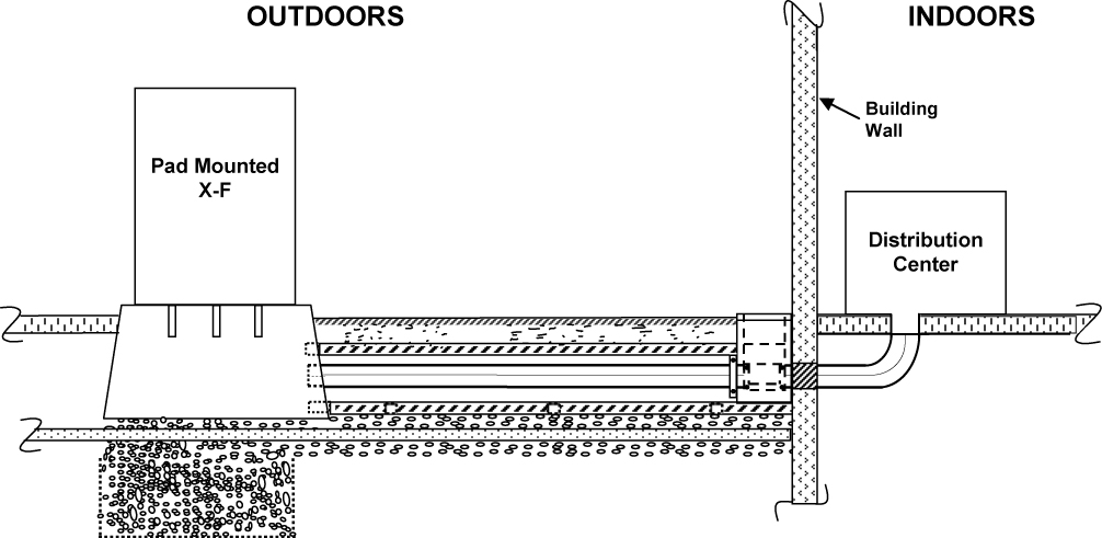
Example of a Below Grade MAXIAMP® Cable Bus System
- Concrete Encasement – Pre-engineered pre-cast steel reinforced MAXIAMP® Cable Bus concrete encasement designed in accordance with industry standard load requirements c/w specially sized and positioned screened air vent openings, removable concrete covers, sectional connecting hardware and also suitable for on-site cutting of circuit angles. (As the result of the flexibility of the sectionalized steel reinforced concrete encasement and the encased MAXIAMP® Cable Bus, ground movement is of no concern with the system reliability and therefore allowing for installation either on ground surface, at ground surface or at any desired depth below ground surface as well as for underwater crossings).
- MAXIAMP® Cable Bus System Unit – All components supplied as in Section A
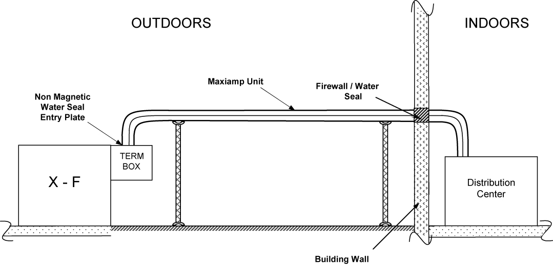
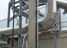
Section C – Combination Below/Above Grade Free Air Ampacity MAXIAMP® Cable Bus System (Proprietary)
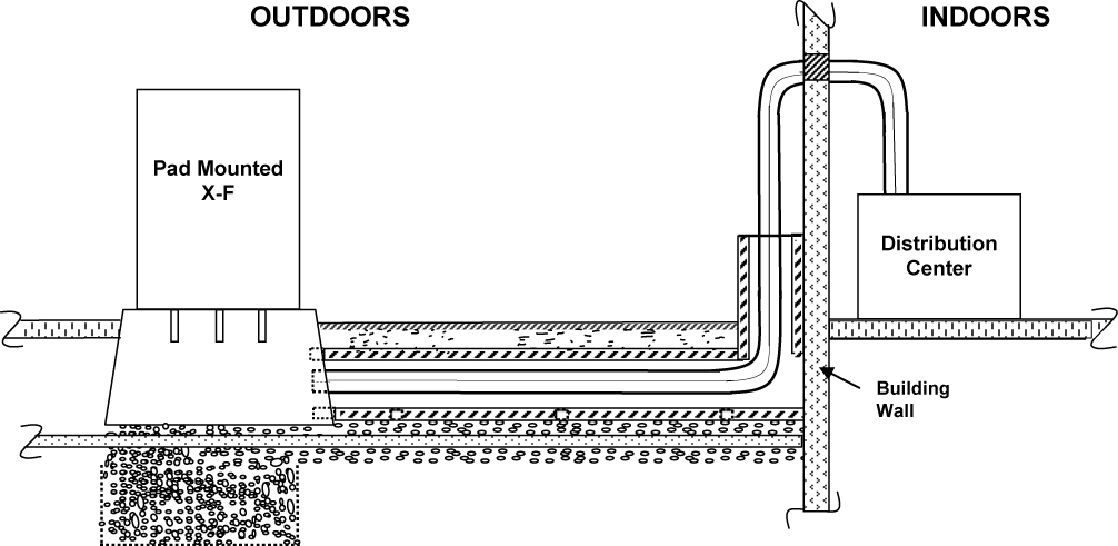
Example of a Below/Above Grade MAXIAMP® Cable Bus System
- Components Supplied –All components stated in Sections (A) and (B), in order to achieve a continuous uninterruptable free air rated cable ampacity power delivery systems from end to end of a circuit route, consisting of sections of overhead and underground installations.
- Vertical Transition Encasements – Vertical pre-cast steel reinforced concrete encasements for transitioning system enclosure from underground to overhead circuit route sections c/w all required hardware and pre-engineered security screens. * Patent Pending
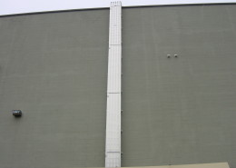
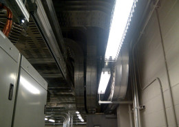
Here are some of the highlight MAXIAMP® Cable Bus Feeder System installations that are currently active.
and here are more installations that have recently been completed
| Advanced Drainage | Gerdau Ameristeel | Polyvalente Ecole |
| Agnico Eagle | Ghost Dam | Poraver North America |
| Apotex | Golden Valley Farms | Pratt & Whitney |
| Atlantic Wallboard | Hydro Quebec | Rosebel Gold Mines |
| Bowaters | Ingersoll Fasteners | Ruetgers Canada |
| Bradken | Irving Oil | Selectra |
| Campeau Drive Pumping Station | JN Precise | Suncor Energy |
| Canadian Salt | Lineman | Thunder Bay Tel |
| Canexus Chemicals Canada LP | London Health Sciences Centre | Tiffin Pier Condominium |
| CKF Inc. | Maple Leaf Foods | Ascent (formerly Tiltran Services) |
| Deslaurier | Marwood Ltd. | Toronto Police Services |
| Diavic Diamond Mines | McGill University | Toyota |
| DMW Electrical | Nova Chemical | Transfreight |
| Dover Flour | Oakrun Farms | Variform |
| Duffin Creek WTP | Pauwels Canada Inc. | Vutec |
| Enwave | PepsiCo | Xstrata Canada |
| Federal Express | Pharmetics | |
| Freightland | Point One Graphics |
1.0 GENERAL
1.1 Scope
This specification applies to the design and supply of the MAXIAMP® Cable Bus Feeder System, which is a power distribution system used to transmit power at the load amperage and voltage specified in an outdoor location for above ground installation.
1.2 General Information
This specification defines the technical requirements related to the design and supply of the MAXIAMP® Cable Bus Feeder System, which shall consist of a ventilated enclosure system, incorporating unarmoured cable, specifically engineered to transmit the required load.
2.0 CODES AND STANDARDS
The components and complete assembly of the MAXIAMP System and its installation shall meet the requirements of the following Standards, as applicable:
- Canadian Electrical Code C22.1 (CE Code Part I)
- Canadian Standards Association
- CSA C22.2 #273 – Cablebus
- CSA C22.2 #38 – Thermoset Insulated Wires and Cables
- CSA C68.10-08 – Shielded power cable for commercial and industrial applications 5 – 46 kV
- UL
- ICEA
- NEMA
3.0 TECHNICAL REQUIREMENTS
3.1 Ventilated Cable Bus Enclosure
3.1.1 Enclosure material
The cable feeder dual level enclosure shall be constructed of high strength, high conductivity, 6063-T6 corrosion resistant aluminum alloy meeting the requirements of CSA C22.2 #126.1, unless otherwise specified.
3.1.2 Enclosure Ventilation
3.1.2.1 The enclosure shall be completely enclosed on both sides, and both top and bottom of the enclosure shall be ventilated with vents that do not expose the MAXIAMP® Cable Bus system nor allow mechanical penetration at 90 degrees from each surface.
3.1.3 Cable Bus Supports Within Enclosure
3.1.3.1 Cables shall be supported within the enclosure and on each level by metal supports which shall be at least 45 mm (1.77”) in width. 3.1.3.2 The metal cable supports shall be repeated throughout the cable enclosure at regular intervals not exceeding 305 mm (12”). 3.1.3.3 Metal supports on each successive vertical cable level shall be longitudinally offset by 1/2 of the support spacing, relative to the supports in the level immediately below.
3.1.4 Cable Bus Clamping Within Enclosure
3.1.4.1 Cable clamps shall be clamped to the metal supports at intervals not exceeding 1143 mm (48”)
3.1.4.2 Cables shall be secured to a cable support by use of a one-piece non-ferrous metal clamp, of width equal to the underlying cable support, providing a trefoil cable arrangement.
3.1.4.3 Each clamp shall be formed to provide a sufficient number of cable ports to secure the designated number of feeder cables
3.2 Power Cables
Each individual power cable shall be of a single, continuous length between terminals, and shall meet the requirements of the appropriate Standard listed in Section 2.0 above, consistent with the system design voltage.
3.2.1 Conductors
Conductors shall be of annealed uncoated Class B stranded copper, sized to meet the current load requirements.
3.2.2 Insulation
MAXIAMP® Cable Bus cable insulation shall be composed of a CSA approved high dielectric elastomeric insulation for voltages 600 volts and greater.
3.2.3 Shielding
3.2.6.1 Strand and insulation shields shall be required on all cables rated 1000 volts or greater.
3.2.6.2 Nonmetallic semiconducting shields shall be of thermosetting material, compatible with the insulation material.
3.2.6.3 Metallic shielding shall consist of overlapped copper tape which is annealed and uncoated.
3.2.4 Jackets
All cables, rated 600 volts and greater, shall be FT-4 rated and shall include a protective jacket.
3.3 Grounding
3.3.1 The enclosure system shall be certified as a continuous bonding conductor, with provision for a ground clamp at each end of each enclosure section.
3.3.2 A bonding conductor shall be connected at a single point to the inside wall of the enclosure system’s top level within each longitudinal section of the enclosure and considered to be an equipment bond. A system grounding conductor, if required, shall be the responsibility of the electrical contractor.
3.4 Weatherproof Plate
If the feeder system termination points are exposed to high levels of moisture (such as rain and sprinkler systems ), a weatherproof plate must be provided to prevent water from penetrating the termination housing. The plate shall be supplied complete by the cable bus manufacturer, pre-assembled with compatible weatherproof cable connectors and pre-drilled mounting holes with mounting hardware.
3.5 Supports
External MAXIAMP® Cable Bus supports shall be designed and provided by others. Cable Bus manufacturer to supply loading requirements.
3.6 Penetration Fire Seals
Where a fire separation is pierced by the enclosure system, all openings around the enclosure and around each individual cable within the enclosure shall be properly closed or sealed with an elastomeric three-hour rated sealing system, in compliance with the National Building Code of Canada.
3.7 Concrete Encasement (for below grade installations)
Provide the precast encasement as designed by the manufacturer to house the MAXIAMP® Cable Bus system. The power and off-set vents are to be positioned in accordance with the manufacturer’s technical requirements. Refer to the attached drawing for additional information – Drawing #5 – Below Transformer and Below Grade Wall Entry
4.0 ACCEPTABLE MANUFACTURERS
Cable Bus shall be the product of United Wire & Cable (MAXIAMP® Cable Bus), or identically equivalent.
5.0 INSTALLATION PROCEDURE
All installations of a MAXIAMP® Cable Bus Feeder System shall be in complete accordance with the manufacturer’s written installation procedure.